By Thomas R. Norris, P.E., and Kier DeAnda
Consultants in Engineering Acoustics
Orinda, California USA
Key Words: silencer, noise, ORC, Organic Rankin Cycle, turboexpander, ORC silencer,
environmental noise, noise reduction, hearing protection, muffler
Abstract
Noise from the outlet pipe of large Organic Rankin Cycle (ORC) turboexpanders can impact acoustical permitting and employee job satisfaction at geothermal power plants. Specific acoustic concerns are environmental permit noise requirements, protection of hearing, and site-wide employee verbal communication ability. Until now, silencers for this service have often degraded within months to a year or two, or they have not provided as much noise reduction as desired. This paper describes progress on a new technology that successfully addresses both issues.
This paper is a progress report, documenting long-term silencing. The reported silencer is based on acoustic resonators, so there are no conventional acoustical materials, a potential problem area. This resonator technology has now been proven satisfactory over a four year period on four nominally 14 MW rated centrifugal Organic Rankin Cycle (ORC) turboexpanders. After four years of use, the silencers show no detected degradation of acoustical performance. Periodic inspections have found no damage, such as cracking due to acoustical fatigue.
The ORC working fluid is isobutane. One silencer was an insert type that could be pushed into an existing pipe. The other three silencers replaced a pipe section. Before silencing, noise levels can be 105-110 dBA at about three feet (about one meter) from the turbine outlet pipe. With the silencer, pipe noise was reduced approximately 20 dBA, and more near the blade passage frequency. Backpressure is judged satisfactory. Acoustic insulation of condenser inlet header piping was not required.
Introduction
A 30 MW geothermal power plant startup occurred in 2009. While startup was successful, neighbors did request that sound levels be reduced. Acoustic studies showed that a common impression was correct – not only was sound from pipes downstream of the turboexpander dominant; it was also the only noise source requiring reduction. Insulation of noisy pipes was not preferred by the owner, because these pipes provide an increment of heat transfer area, and these pipes also had required direct visual inspections due to sonic fatigue and other vibration concerns.
A turboexpander is another name for a centrifugal turbine, basically a centrifugal fan or pump run in reverse. However, a turboexpander is sophisticated, has a high rpm, and uses variable inlet nozzles to keep pressure and velocity within desired ranges as flow conditions vary. Geothermal service, especially if the condensers are air cooled, will show wide variations in turbine exhaust pressure, so highly refined turboexpander designs are needed. These designs, while efficient, can generate significant noise near the downstream exhaust pipes.
Description of Silencers
Two designs were installed. The first design is an acoustical element insert, intended to be installed into a section of the existing 36 inch outside diameter (0.914 meter) diffuser outlet pipe. The second design is a complete silencer of 42 inches (1.07 meter) in outside diameter, so is an expanded section of pipe with a gradual conical inlet. The first silencer installed was the insert type, and the other three were complete silencers. Acoustical performance is about equal for both types. The larger diameter silencer has lower flow velocity and thus, is predicted to have lower backpressure compared to the insert. However, the complete silencer weighs more than the simple insert, so has higher fabrication and material costs.
The available space for a silencer is about 18 feet long, longer than needed for a silencer, so a section is potentially unused. Since this pipe section was available, this section received an acoustical liner also made of resonators to provide some additional noise reduction. This acoustical liner cost was small compared to the silencer proper, and is believed a good investment.
Figure 1 shows a section view of the silencer. It consists of the outer pressure pipe, and two concentric rings within. Supports are not shown. The acoustical resonator elements are shown as dashed lines.
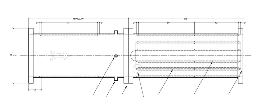
Dimensions are in inches. Flow is left to right.
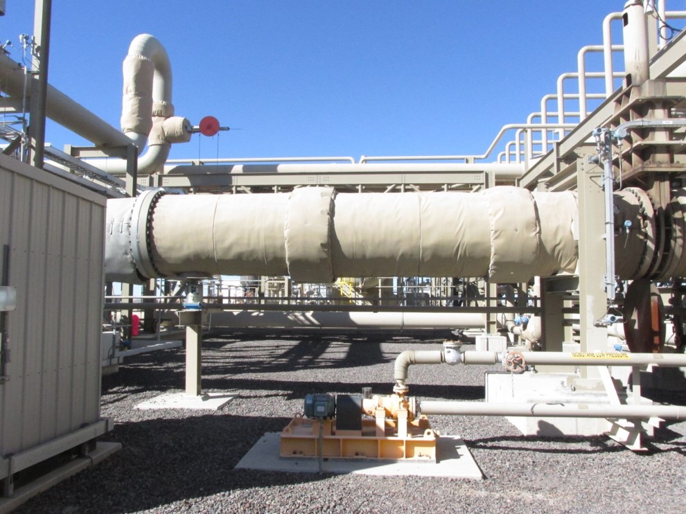
Figure 2 is a March 2015 dated photo of the in service silencer, in an insulated jacket. The turboexpander is to the right, and flow is from right to left. The turbine outlet diffuser is the conical section of pipe attached to the turboexpander. The silencer, in center of photo, is bolted directly to the outlet end of the diffuser cone flange. On the left side of photo is a vertical riser pipe with an expansion joint. Just out of the photo, this vertical pipe leads to a “Tee” junction and elevated condenser “header” pipe. The large header pipe runs the full length of the condenser, and is not insulated. Small purple rectangles on bottom of silencer in the photo are noise measurement positions used in 2015.
Acoustical Design Issues
The dominant power plant sound, if no silencers are used, is noise emitted by the turbine outlet pipe surfaces. This sound is perceived as a “roar” with some tonality. The tone at the turbine blade pass frequency and next two harmonics are not prominent enough to be audible as tones, but (to the authors) seem part of the roar. The uneven spectrum shape, in the authors’ subjective judgement, causes a distinctive, slightly “hollow” sound.
Backpressure
Backpressure is always an economic concern in silencers. Backpressure was estimated to be below 0.5 psi, but was not measured.
The following three silencers were installed and later checked for acoustic performance. Sound levels were measured at ear height under the elevated condenser inlet “header” pipe. Unfortunately, there are no directly comparable before and after noise measurements from which to evaluate the noise reductions achieved. However, there are “clean” data that comparing 2010 and 2015 sound levels.
Test Results
The noise reduction achieved in 2010 has not degraded four years later, in 2015.
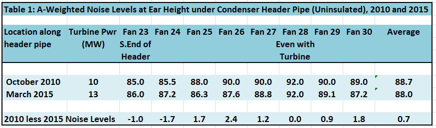
Table 1 shows noise levels in dBA measured at ear height for a person walking on the ground under the long, elevated condenser header pipe. The “Fan Numbers” refer to the large fans of the Air Cooled Condenser. The data were collected in November of 2010 and again in March of 2015. The silencer was already installed before the first measurements.
The last line in this table shows the noise level differences between 2010 and 2015 at each location. Any degradation in silencer performance would show up as a noise increase in 2015, compared to 2010. There are no significant increases shown. The average is a 0.7 dB decrease, compared to 2010. This is difference is judged by the authors as not significant. Sound levels nearest the turbine outlet pipe show slightly higher noise in 2010 than in 2015. This is believed due reasons mentioned below.
Known insulation and operation differences between 2010 and 2015 are:
In 2010, insulation on the silencer and adjacent pipes had been pulled away at several seams to allow close-up measurements of locally uninsulated, pipe-emitted noise. This emitted noise would have contributed a small increment (two dB or less, most likely) at the closest measurement locations in 2010, but not 2015 without these gaps.
In 2010, turbine power was about 10 MW, and in 2015, between 13 and 14 MW (Higher power is known to increase outlet pipe noise, see next item.) In 2015, the pressure ratio across the turbine was near 5.5 to 1, but was less in 2010. (Higher pressure ratio is known to increase outlet pipe noise.) Pump noise was prominent near the south end of the header in 2015, but not noted in 2010.
The maximum noise level difference is 2.4 dB louder in 2010, at the location closest to the silencer. This location is directly under a “T” junction where the turbine outlet pipe and silencer joins the condenser header pipe at its mid-point. This location receives noise from the uninsulated overhead header pipe, but also receives noise from the close-by turbine outlet pipe. The acoustical insulation on the turbine and silencer was fastened tightly in 2015, but was pulled apart locally at a seam in 2010, leaving several exposed noise-emitting gaps about 6 inches wide along the bottom of the silencer. Resulting noise emission would increase noise measured under the header, and was plainly audible there in 2010.
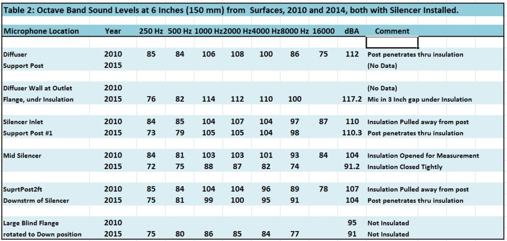
Table 2 documents octave band and A-weighted sound levels close to the silencer. The right-most column is the A-weighted noise levels at 6-inches distance from exposed steel pipe surfaces. The lowest sound levels shown is 104 dBA, confirming that silencer shell and pipe noise is still of concern.
Future Development
The silencer technology is under continuing development to address cost, and further attenuation.
Conclusion
The noise changes over time shown on Table 1 are well within the differences expected only due measurement uncertainty and to the changes in plant operating and insulation conditions noted, and not due to increases or decreases in silencer attenuation performance. The silencer continues to provide satisfactory noise reduction after four years of operation. Inspections have reported no known physical degradation.
Acknowledgements
We acknowledge with gratitude the help of the power plant owner, who wishes to remain anonymous, for authorizing the silencer design and installations, for allowing the recent measurements, and for giving permission to publish. We also acknowledge Colorado TBC for fabricating and installing those components subject to pressure vessel code requirements, and for expert advice in technical areas that are not within our field of experience. Without these many contributions, neither the silencers nor this technical progress report would have been possible.